
- Overview
- Recommended Products
Place of Origin: |
China |
Brand Name: |
Wago Dingyi |
Model Number: |
WGHPA series AC analog power grid power supply |
Certification: |
GB/T19001-2016/ISO 9001:2015 CNAS CMA |
Minimum Order Quantity: |
1 |
Delivery Time: |
80 days |
Description:
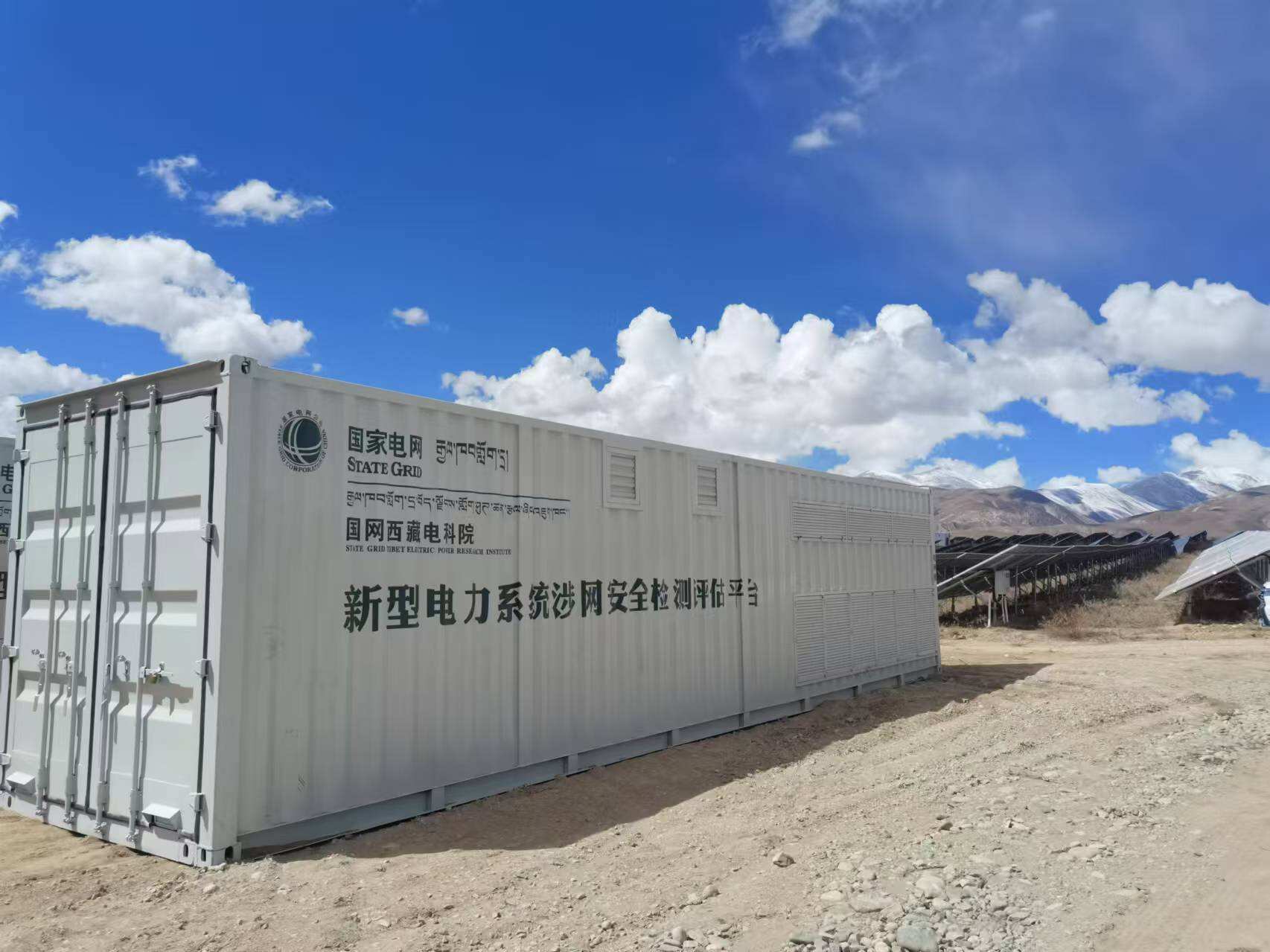
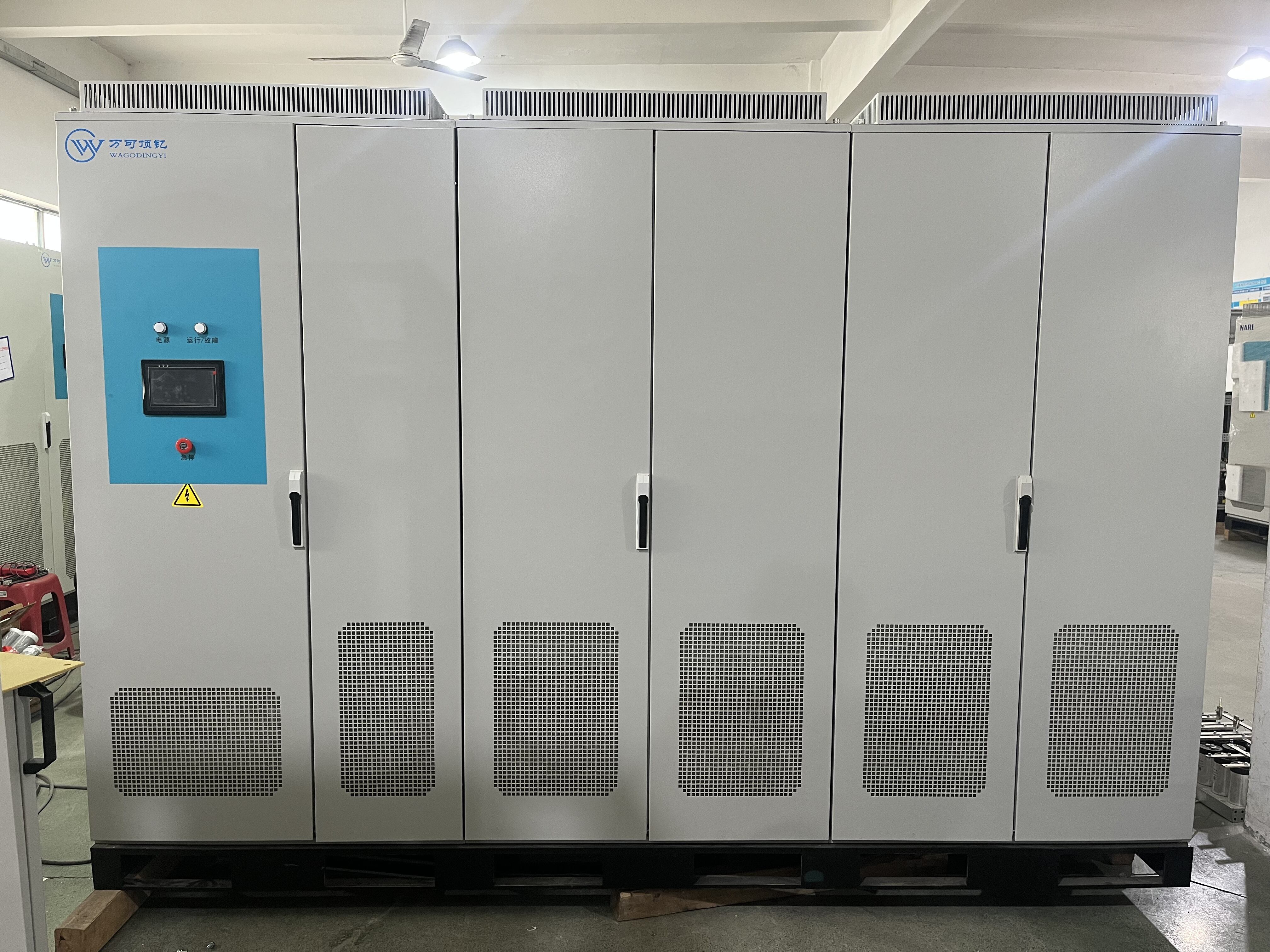
The grid simulation equipment takes the actual power grid as a model and realizes the bidirectional energy flow by adopting the grid-connected feedback principle and the full-digital vector control technology with DSP real-time processing. The simulation of power grid characteristics is achieved through the DSP's full-digital algorithm.
Specifications:
Overall efficiency |
90%(loaded condition) |
Isolation method |
Magnetic isolation (built-in isolation transformer) |
Cooling method |
forced air cooling |
Feedback capability |
100% energy feedback |
Input voltage |
AC 400V ± 10% / AC 690V ± 10% (line voltage) |
Input connection method |
3P3W+G |
Input frequency |
50Hz ±5% |
Input power factor formula |
Greater than 0.98 (above half-load) |
Input current harmonic distortion rate |
1. Under rated conditions, the current harmonics fed back to the power grid are less than 5% (above half-load). 2. Within the full power range, the effective value of the generated harmonics does not exceed the absolute value under rated conditions. |
Power quality requirements |
When the power quality of the power grid meets the requirements of the national standard GB/T12325-2003 for power quality - allowable deviation of power supply voltage, and GB/T14549 for power quality - harmonics in the public power grid, the device can operate normally; for applications with poor power quality, due to the adoption of PWM rectification technology, it can have strong adaptability. |
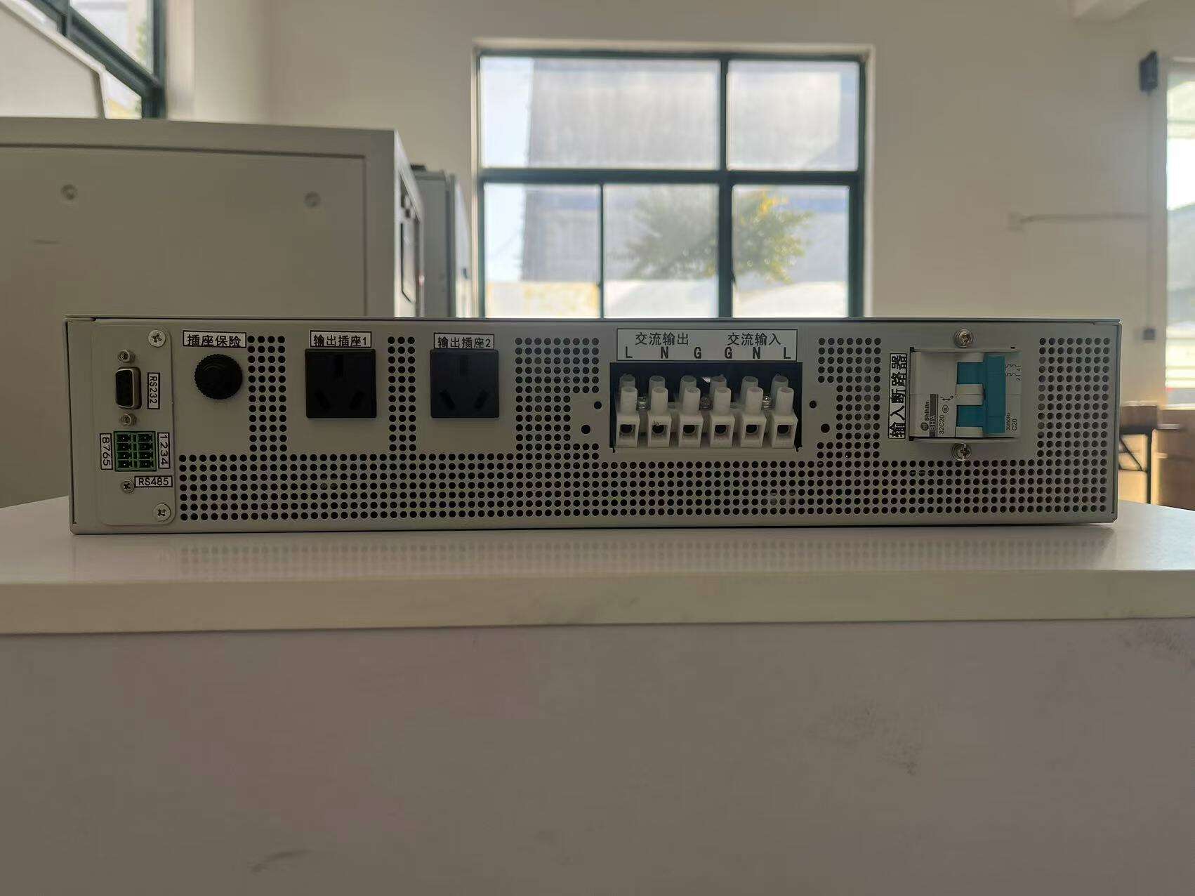
Output connection mode |
3P4W |
Voltage indicators |
1. Stability: Less than (0.2% + 0.2% FS) 2. Adjustment accuracy: 0.2% + 0.2% FS 3. Load voltage regulation rate: The amplitude of steady-state voltage fluctuation is less than ±0.5V 4. Voltage change speed: Greater than 100V/ms 5. Output voltage THD: Less than 50% of the harmonic value required by GB/T14549, less than 1% (linear load) 6. Three-phase unbalance voltage regulation force: 100% |
Current indicators |
Display accuracy :0.2%+0.2%FS |
Frequency indicators |
1. Adjustment range: 30 - 100 Hz 2. Adjustment step: 0.01 Hz 3. Frequency stability rate: The steady-state frequency fluctuation value is less than ±0.005 Hz. Frequency adjustment accuracy: 0.005 Hz |
Harmonic, inter-harmonic, sub-harmonic indicators |
1. Harmonic injection range: Up to 50 times. 2. Inter-harmonic injection range: 5 - 2500Hz. 3. Injection quantity: 50 different harmonics are injected simultaneously. 4. Harmonic content: 8% for odd harmonics, 4% for even harmonics, and the total harmonic distortion rate can reach up to 15%. 5. Injection accuracy: <1%. |
Three-phase unbalance simulation function |
1. The device can simulate and output unbalanced three-phase voltage. 2. The regulation degree of three-phase unbalanced voltage: 100% 3. Output phase angle: continuously adjustable from 0° to 359° 4. Phase angle error: < ±1.5 degrees (under normal working conditions) 5. Output phase angle: The starting phase angle can be set during the test (including zero-crossing point) 6. Phase angle adjustment step: 0.1° |
Programmable output (step, gradual change) |
1. The minimum programming time is 5ms, and the maximum programming time is 999 hours. The programming step size is 1ms. 2. Voltage, frequency and phase can be programmed and set. Stepwise or gradual change methods are selectable. The programming data can be run in a loop. 3. While conducting the experimental steps, there is a set of isolated virtual synchronous signal output. 4. Voltage fluctuation immunity, frequency fluctuation immunity, voltage harmonic and inter-harmonic tests can be carried out. Voltage fluctuation and flicker tests can be conducted using data programming. 5. Low-pass and high-pass memories can be set. |
Low voltage ride-through index |
1. Drop depth: Drop to 5% of the working voltage. 2. Dynamic time: Less than 1ms. 3. Unbalanced drop: Equipped with independent drop functions for single phase and two phases. |
High voltage ride-through index |
1. Rise amplitude: Rise to 135% of the working voltage. 2. Dynamic time: Less than 1ms. 3. Unbalanced high current: Equipped with single-phase/two-phase independent high current passing function. |
Zero voltage ride-through index |
1. Drop range: drop to 0V voltage. 2. Dynamic time :<1ms. 3. Unbalanced zero: with single-phase/two-phase independent zero penetration function. |
Phase angle transformation index |
1. Transformation range: Maximum 180 degrees can be transformed online. 2. Dynamic time: Less than 1ms. 3. Unbalance transformation: It has the function of independent single-phase/two-phase transformation. |
Protection function |
Input under-frequency, input under-voltage, input over-current, IGBT over-current, DC bus over-voltage; output over-current, short-circuit protection, output over-voltage, magnetic component over-temperature. |
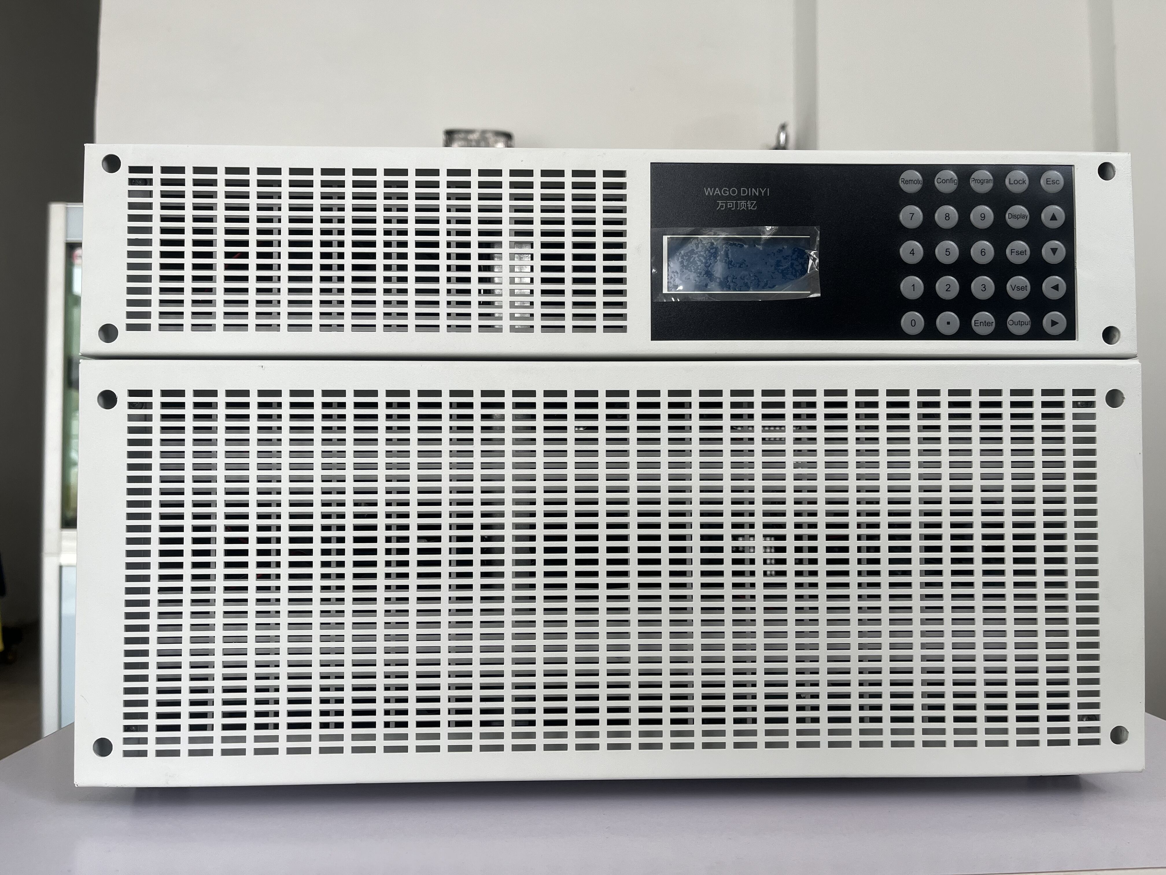
Hardware |
Touch screen/remote computer |
Display parameters |
Output voltage (3-phase), output current (3-phase), output frequency, output phase (3-phase), output active power (3-phase), output power factor (3-phase), output voltage peak coefficient (3-phase), output current peak coefficient (3-phase), bus voltage, bus current |
Communication method |
ModbusTCP/Mod bus RTU |
Display voltage resolution |
士0.2%FS |
Display current resolution |
士0.2%FS |
Display power resolution |
士0.4%FS |
Display frequency resolution |
士0.001HZ |
Protection level |
Basic structure shall not be lower than IP20 |
Operating environment |
Indoor |
Altitude |
Not exceeding 1500m |
Operating environment temperature |
-10~45°C |
Relative air humidity |
0 - 95% (no condensation) |
Application domain:
1.It is used to test the performance and compatibility of new energy power generation devices such as solar and wind power, and to evaluate them under different grid conditions through simulation.
2. Provide a simulated power grid environment for the research and experimentation of smart grid-related technologies.
3. Assist in the research and development as well as the verification of the functions and reliability of various power electronic devices, converters, etc.
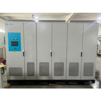
Characteristics:
1. Equipped with a large-screen LCD display, it can show multiple data that need to be monitored, such as voltage, current, active power, reactive power, power factor, peak factor, etc.
2. It has perfect protection functions: over-power, over-current, over-voltage, short circuit, over-temperature, etc.
3. The equipment communication uses WIFI connection to achieve separation of control and high-voltage power unit, making the test safer.
4.It has RJ45/RS485 communication interface, supports Mod bus TCP and Mod bus RT U protocol, and has perfect remote operation software.