
- Overview
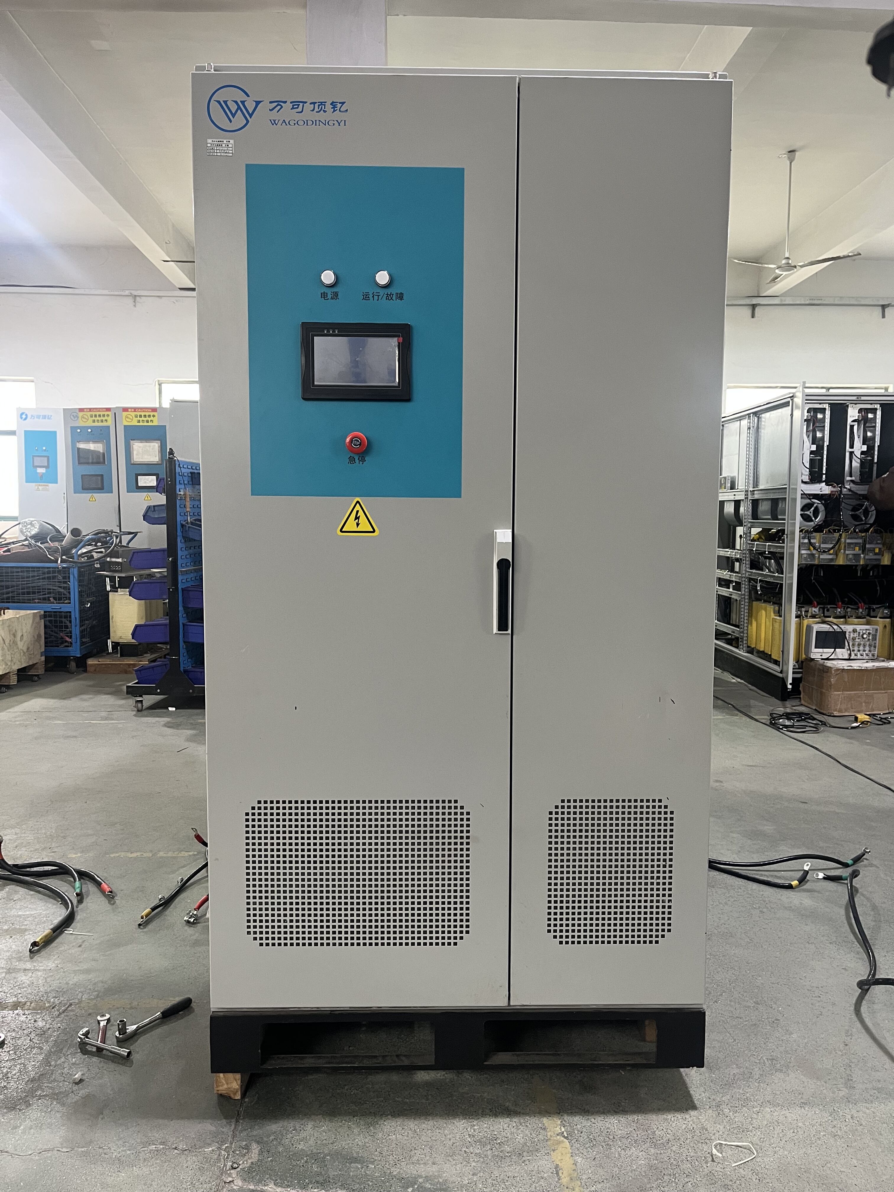
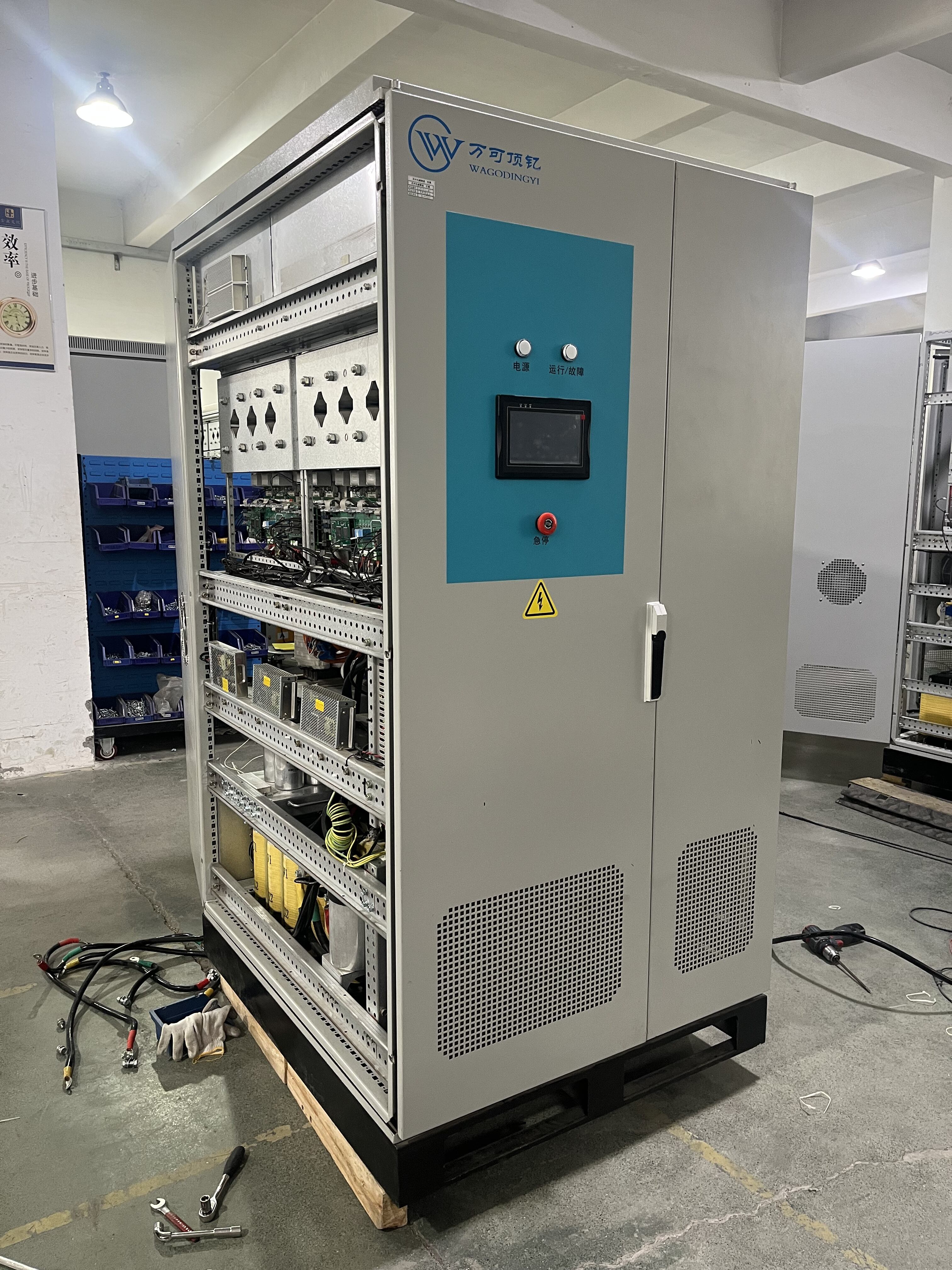
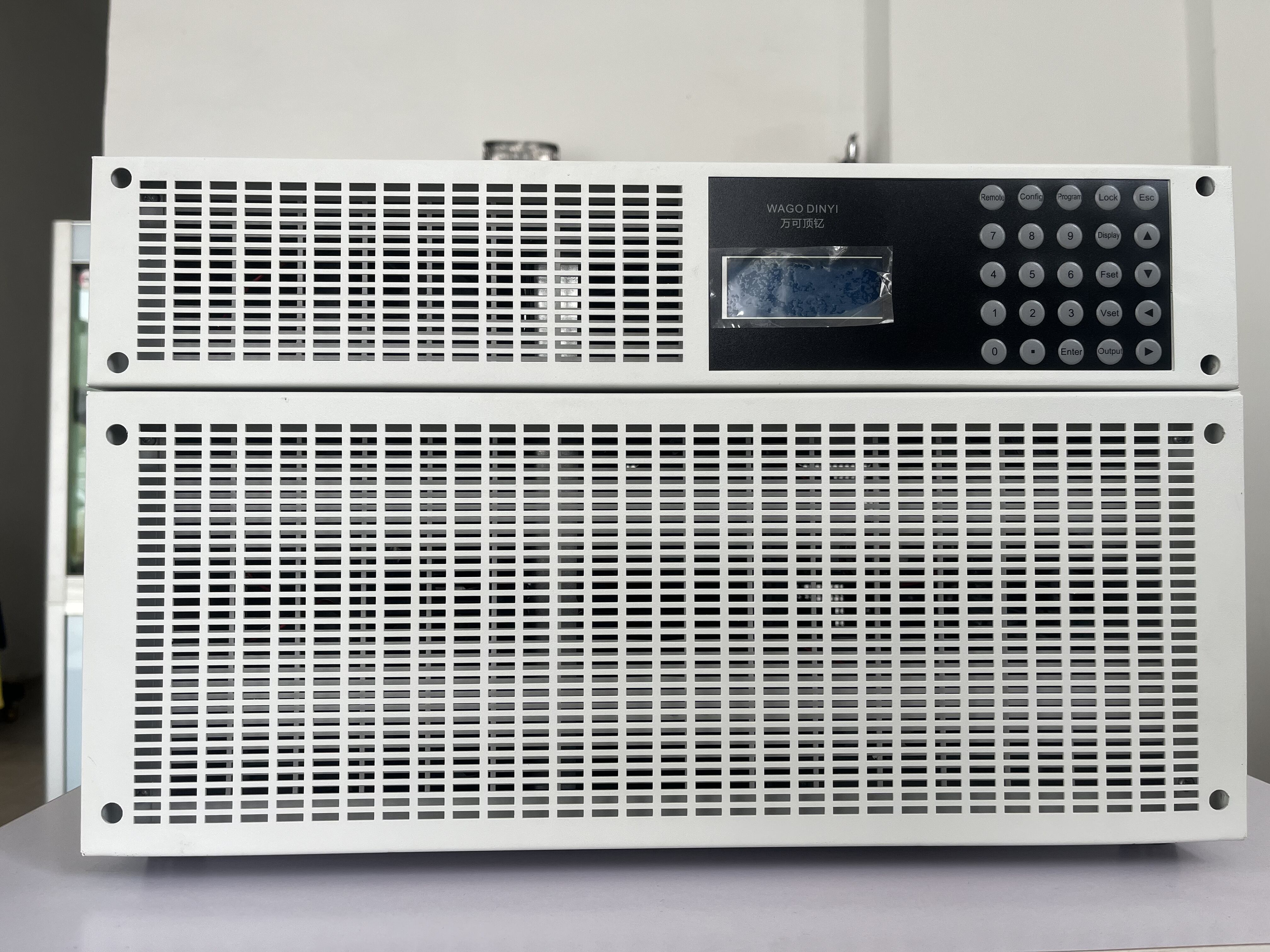
- Recommended Products
- Two gear modes of 0~13kV/0~45.5kV
- The voltage response time is less than 5ms
- The total harmonic distortion of the output voltage is less than 1%.
- Stability: 0.1%FS at 35kV/10kV end
- Adjustment accuracy: 0.1% of Full Scale at 35k/10kV terminals.
- Negative load regulation rate; steady-state voltage fluctuation amplitude is less than ±0.5% Un
- Change speed :
Place of Origin: |
China |
Brand Name: |
Wago Dingyi |
Model Number: |
|
Certification: |
GB/T19001-2016/ISO9001:2015 CNAS CMA |
Minimum Order Quantity: |
1 |
Delivery Time: |
90 days |
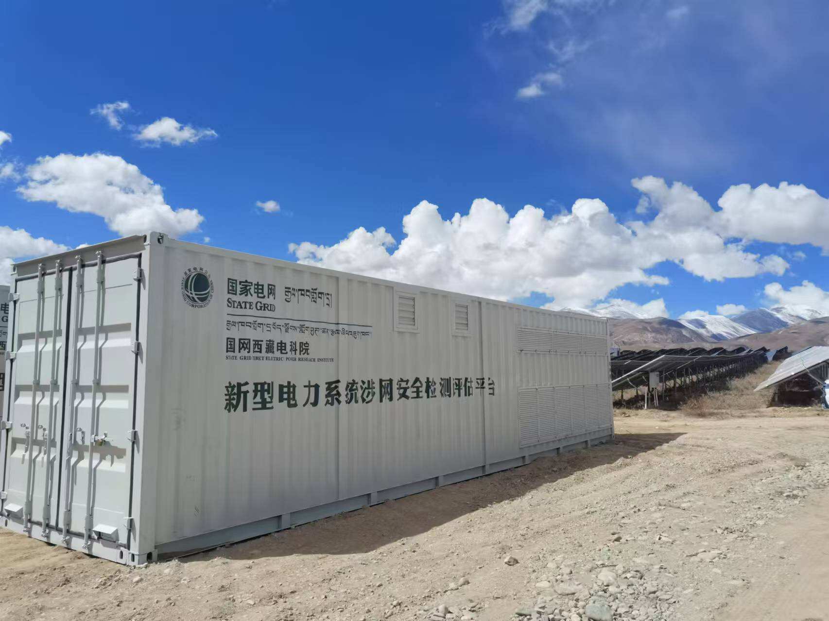
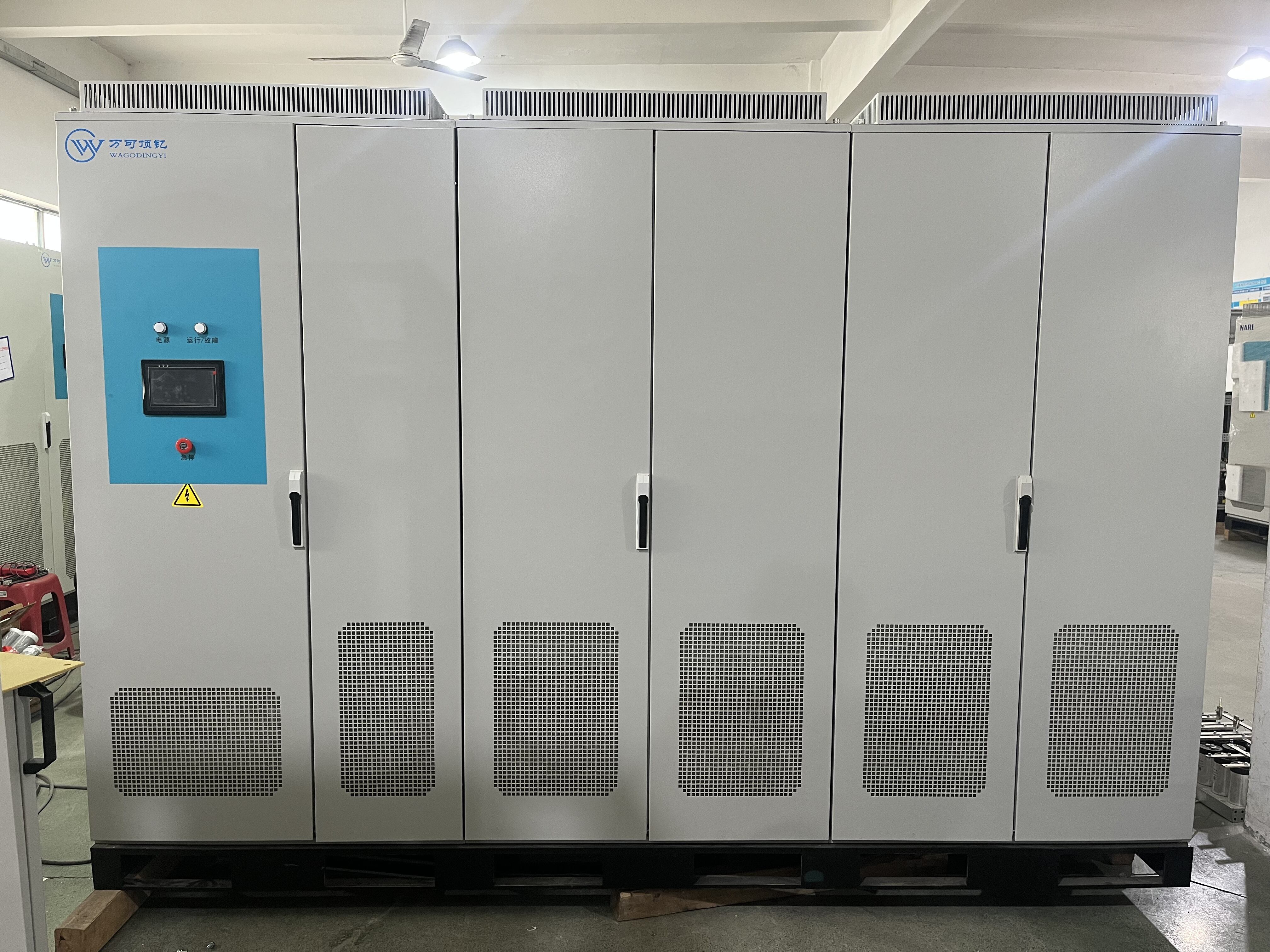
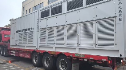
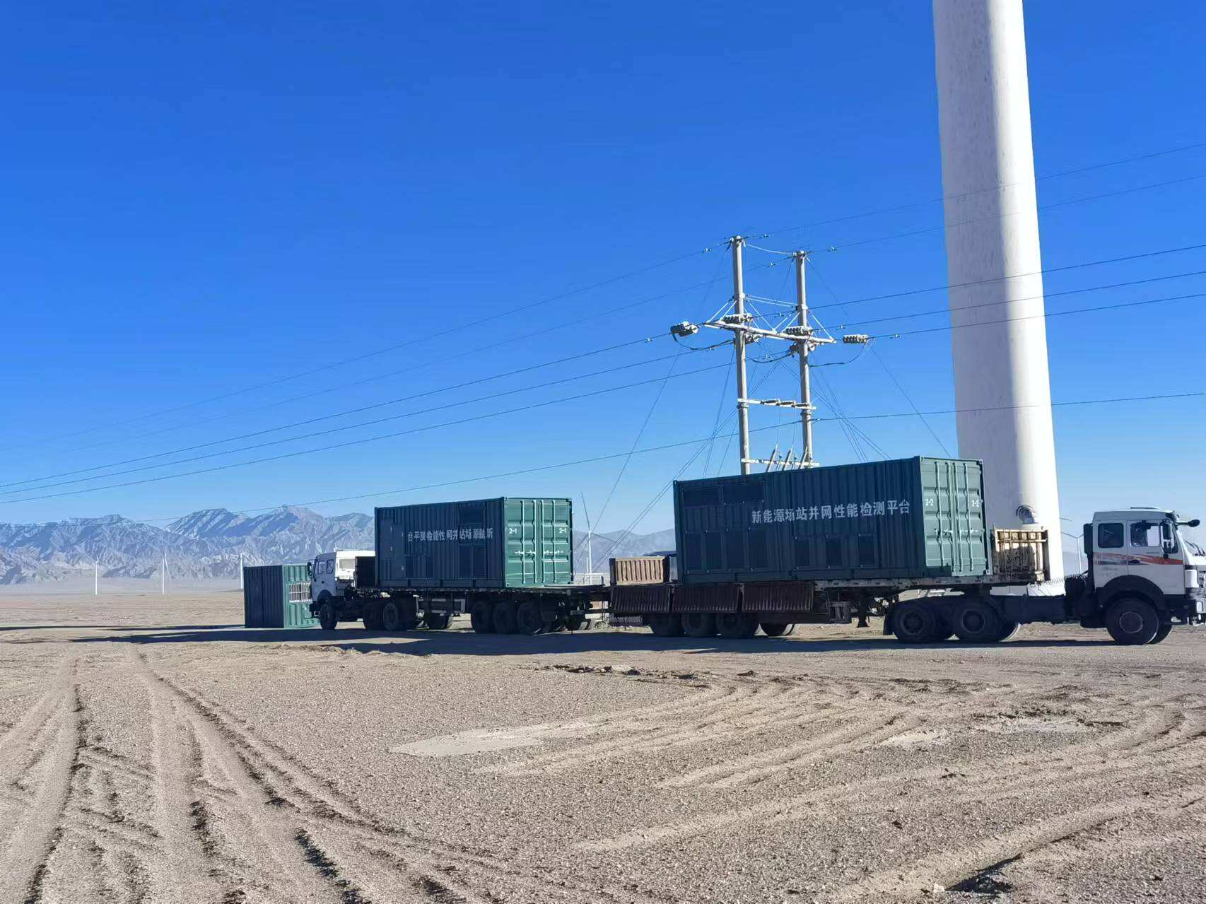
Description:The CWLPA series mobile vehicle-mounted grid disturbance simulation device is pre-installed in a container. It adopts the grid-connected feedback principle and the full digital vector control technology based on DSP real-time processing, taking the actual grid as the model, to achieve bidirectional energy flow. Through the DSP full digital algorithm, it can simulate the characteristics of the grid and conduct voltage/frequency deviation, three-phase imbalance, voltage flicker, grid harmonics and other voltage adaptability tests on the tested power station; as well as symmetrical and asymmetrical high and low voltage ride-through, continuous ride-through and other fault ride-through tests.
Specifications:
Rated capacity |
5000kva |
Overall efficiency |
Greater than 90% (in full load condition) |
Isolation method |
Magnetic isolation |
Heat dissipation method |
forced cooling |
Feedback capability |
100% energy feedback |
Input voltage |
AC 10KV/35KV+10% |
Input connection method |
3P3W+G |
Input frequency |
50HZ+ 5% |
Input power factor |
0.98(over half load) |
Output connection method |
3P3W |
Output voltage |
|
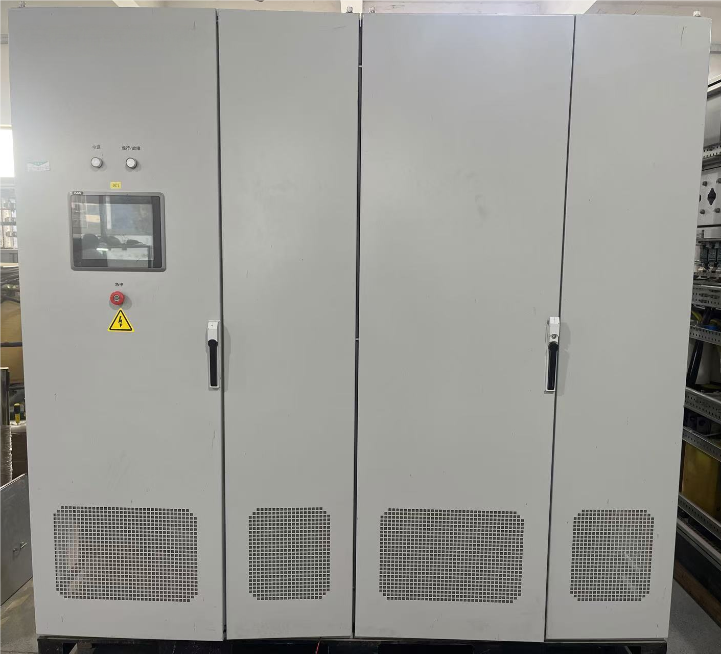
Human-machine interaction |
Touch screen / remote computer |
Display parameters |
Output voltage (3-phase), output current (3-phase), output frequency, output phase (3-phase), output active power (3-phase), output power factor (3-phase), bus voltage, bus current, etc. |
Display resolution |
Voltage, current, power :±0.2%FS Frequency: 0.001HZ |
Protection grade |
The basic structure is not less than IP54 |
Operating environment |
Car mobile outdoor use |
Salt spray conditions Altitude |
The surface of the container uses anti-rust primer and outdoor paint, with strong corrosion resistance |
Working environment temperature |
3000m; Above 3000m, it complies with the provisions of GB/T3859.2-2013 and can be used at reduced capacity within the temperature range of -25 to 40 °C. |
Rated capacity |
0.001Un/ms~0.2Un/ms |
Current indicators |
Display accuracy :0.2%+0.2%FS |
Frequency indicators |
1. Adjustment range: 45 - 65Hz 2. Adjustment step size: 0.01Hz 3. Frequency stability rate: The fluctuation of the steady-state frequency is less than +0.005Hz 4. Frequency adjustment accuracy: 0.005Hz |
Harmonic, inter-harmonic, sub-harmonic indicators |
1. Harmonic injection range: Up to 25 times at maximum 2. Inter-harmonic injection range: 5 - 1250Hz 3. Injection quantity: Simultaneous injection of 10 different harmonics 4. Harmonic content: 8% for odd harmonics, 4% for even harmonics, and the variation rate of total harmonics can reach up to 15%. 5. Injection accuracy: <0.2%. |
Three-phase imbalance simulation function |
1. The device can simulate output of unbalanced three-phase voltage with the regulation force of three-phase unbalanced voltage being 100%. 2. Voltage can be adjusted in single phase. When adjusting single-phase voltage, the amplitude changes of the other two phases are less than 1% of the rated value (in line with the requirements of low and high insulation resistance). 3. Output phase angle: adjustable continuously from 0 to 360°. 4. Phase angle deviation: <±1.5 degrees (under normal working conditions). 5. Output phase angle: the starting phase angle can be set during the test (including the zero-crossing point). 6. Phase angle adjustment step: 0.1 degree. |
Programmable output |
1. The minimum programming time is 5ms, the maximum programming time is 999 hours, and the programming step is 1ms. 2. Voltage, frequency, and phase can be programmed and set. The programming data can be run in a loop. There are two options for step change: step change and gradual change. A group of virtual synchronous signals with a delay can be output simultaneously during the experimental steps. 3. While conducting the experimental steps, a set of delayed virtual synchronous signals can be output. 4. The memory for low current and high current can be set. |
defensive function |
Input over-frequency, input over-voltage, input over-current, IGBT over-current, DC bus over-voltage; output over-current. Short-circuit protection, output over-voltage, overheating of magnetic components. |
Applications:
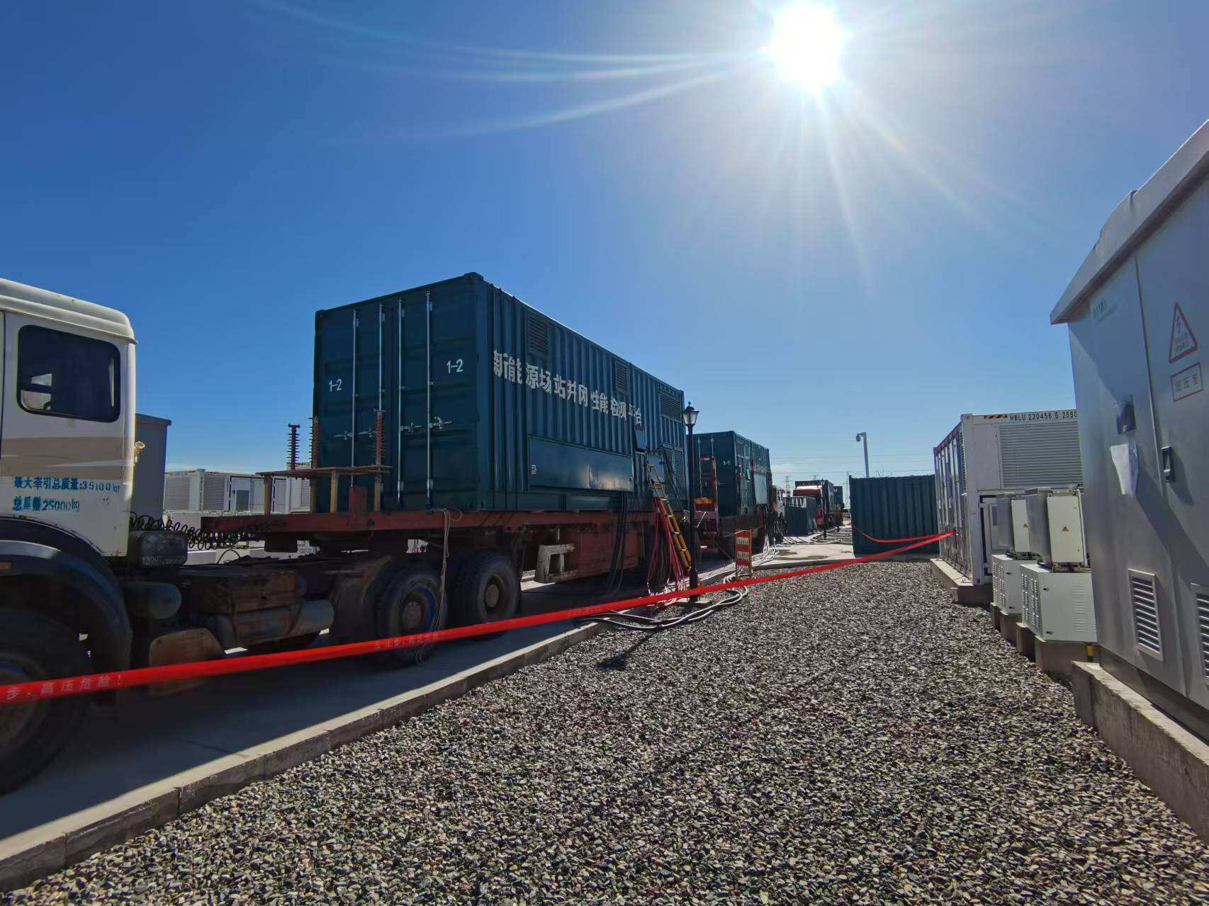
(application industry)The CWLPA series mobile vehicle-mounted grid disturbance simulation device meets the testing capabilities required for the detection and certification of photovoltaic, energy storage, wind power and other new energy power stations. It is usually connected in series to the collector lines of new energy power stations, with the output side connected to the high-voltage side of the transformer box of the new energy power generation unit. By changing the output parameters, it simulates the changes in the grid to test the power stations.
(Equipment test function)
1. Voltage adaptability test
2. Fluctuation adaptability test
3. Frequency adaptability test
4. Harmonic voltage adaptability test
5. Three-phase voltage unbalance adaptability test
6. High voltage penetration test (symmetrical and asymmetrical)
7. Zero voltage penetration test (symmetrical and asymmetrical)
8. Low voltage penetration test (symmetrical and asymmetrical)
9. Continuous penetration test (symmetrical and asymmetrical)
Technical features
1. The equipment is pre-installed in containers and is suitable for outdoor use. It has good corrosion resistance and is convenient and reliable for transportation.
2. It supports multiple units of the same model to be connected in parallel, with a maximum of 10 units that can be connected in parallel.
3. In the parallel mode using the high-voltage side, only the high-voltage parallel cable needs to be connected during parallel operation, without the need to connect the low-voltage side cable. The wiring is less and the testing efficiency is high.
4. The voltage on the high-voltage side is used as the control loop parameter, with strong load capacity and high output voltage accuracy (the high-voltage side accuracy is not less than 0.1% F.S.).
5. Voltage programming can achieve rapid response (response time less than 1ms).
6. It has the ability to simulate grid waveform distortion, with high harmonic accuracy (accuracy higher than 0.5%) when outputting 2-25 harmonic components.
7. The mature digital control technology and complete hardware filtering circuits make the voltage and current harmonic content low, and the waveform distortion rate small (the high-voltage side voltage harmonic is less than 1%).
8. A large-screen LCD screen is used, which can display multiple data that need to be monitored, such as voltage, current, active power, reactive power, power factor, peak factor, etc.
9. It has complete protection functions: overpower, overcurrent, overvoltage, short circuit, overtemperature, etc.
10. The equipment communication uses WIFI connection to achieve separation of control and high-voltage power unit, making the testing safer.